In this Azure Networking deep dive, I’m going to share some of my experience around planning the creation and association of Route Tables in Microsoft Azure.
Quick Recap
The purpose of a Route Table is to apply User-Defined Routes (UDRs). The Route Table is associated with a subnet. The UDRs in the Route Table are applied to the NICs in the subnet. The UDRs override System and/or BGP routes to force routes on outgoing packets to match your desired flows or security patterns.
Remember: There are no subnets or default gateways in Azure; the NIC is the router and packets go directly from the source NIC t the destination NIC. A route can be used to alter that direct flow and force the packets through a desired next hop, such as a firewall, before continuing to the destination.
Route Table Association
A Route Table is associated with one or more subnets. The purpose of this is to cause the UDRs of the Route Table to be deployed to the NICs that are connected to the subnet(s).
Technically speaking, there is nothing wrong with asosciating a single Route Table with more than one subnet. But I would the wisdom of this practice.1:N
1:N Association
The concept here is that one creates a single Route Table that will be used across many subnets. The desire is to reduce effort – there is no cost saving because Route Tables are free:
You create a Route Table
You add all the required UDRs for your subnets
You associate the Route Table with the subnets
It all sounds good until you realise:
That individual subnets can require different routes. For example a simple subnet containing some compute might only require a route for 0.0.0.0/0 to use a firewall as a next hop. On the other hand, a subnet containing VNet-integrated API Management might require 60+ routes. Your security model at this point can become complicated, unpredictable, and contradictory.
Centrally managing network resources, such as Route Tables, for sharing and “quality control” contradicts one of the main purposes of The Cloud: self-service. Watch how quick the IT staff that the business does listen to (the devs) rebel against what you attempt to force upon them! Cloud is how you work, not where you work.
Certain security models won’t work.
1:1 Association
The purpose of 1:1 association is to:
Enable granular routing configuration; routes are generated for each subnet depending on the resource/networking/security requirements of the subnet.
Enable self-service for developers/operators.
The downside is that you can end up with a lot of subnets – keep in mind that some people create too many subnets. One might argue that this is a lot of effort but I would counter that by saying:
I can automate the creation of Route Tables using several means including infrastructure-as-code (IaC), Azure Policy, or even Azure Virtual Network Manager (with it’s new per-VNet pricing model).
Most subnets will have just one UDR: 0.0.0.0/0 via the firewall.
What Do I Do & Recommend?
I use the approach of 1:1 association. Each subnet, subject to support, gets its own Route Table. The Route Table is named after the VNet/subnet and is associatded only with that subnet.
I’ve been using that approach for as long as I can remember. It was formalised 6 years ago and it has worked for at scale. As I stated, it’s no effort because the creation/association of the Route Tables is automated. The real benefit is the predictability of the resulting security model.
In this post, I want to explain why routing is so important in Microsoft Azure. Without truly understanding routing, and implementing predictable and scaleable routing, you do not have a secure network. What one needs to understand is that routing is the security cabling of Azure.
My Favourite Interview Question
Now and then, I am asked to do a technical interview of a new candidate at my employer. I enjoy doing technical interviews because you get to have a deep tech chat with someone who is on their career journey. Sometimes is a hopeful youngster who is still new to the business but demonstrates an ability and a desire to learn – they’re a great find by the way. Sometimes its a veteran that you learn something from. And sometimes, they fall into the trap of discussing my favourite Azure topic: routing.
Before I continue, I should warn potential interviewees that the thing I dislike most in a candidate is when they talk about things that “happened while I was there” and then they claim to be experts in that stuff.
The candidate will say “I deployed a firewall in Azure”. The little demon on my shoulder says “ask them, ask them, ASK THEM!”. I can’t help myself – “How did you make traffic go through the firewall?”. The wrong answer here is: “it just did”.
Look at that beauty. You’ve got Azure networks in the middle (hub) and the right (spoke). And on the left is the remote network connected by some kind of site-to-site networking. The deployment even has the rarely used and pricey Network SKU of DDoS protection. Fantastic! Security is important!
And to re-emphasise that security is important, the firewall (it doesn’t matter what brand you choose in this scenario) is slap-bang in the middle of the whole thing. Not only is that firewall important, but all traffic will have to go through it – nothing happens in that network without the firewall controlling it.
Except, that the firewall is seeing absolutely no traffic at all.
Everything is a VM in the platform, including NVA routers and Virtual Network Gateways (2 VMs).
Packets always route directly from the source NIC to the destination NIC.
In our above firewall scenario, let’s consider two routes:
Traffic from a client in the remote site to an Azure service in the spoke.
A response from the service in the Azure spoke to the client in the remote site.
The client sends traffic from the remote site across the site-to-site connection. The physical part of that network is the familiar flow that you’d see in tracert. Things change once that packet hits Azure. The site-to-site connection terminates in the NVA/virtual network gateway. Now the packet needs to route to the service in the spoke. The scenario is that the NVA/virtual network gateway is the source (in Azure networking) and the spoke service is the destination. The packet leaves the NIC of the NVA/virtual network and routes directly (via the underlying physical Azure network) directly to the NIC of one of the load-balanced VMs in the spoke. The packet did not route through the firewall. The packet did not go through a default gateway. The packet did not go across some virtual peering wire. Repeat it after me:
Packets route directly from source to destination.
Now for the response. The VM in the spoke is going to send a response. Where will that response go? You might say “The firewall is in the middle of the diagram, Aidan. It’s obvious!”. Remember:
Packets route directly from source to destination.
In this scenario, the destination is the NVA/virtual network gateway. The packet will leave the VM in the spoke and appear in the NIC of the NCA/virtual network gateway.
It doesn’t matter how pretty your Visio is (Draw.io is a million times better, by the way – thanks for the tip, Haakon). It doesn’t matter what your intention was. Packets … route directly from source to destination.
User-Defined Routes – Right?
You might be saying, “Duh, Aidan, User-Defined Routes (UDRs) in Route Tables will solve this”. You’re sort of on the right track – maybe even mostly there. But I know from talking to many people over the years, that they completely overlook that there are two (I’d argue three) other sources of routes in Azure. Those other routes are playing a role here that you’re not appreciating and if you do not configure your UDRs/Route Tables correctly you’ll either change nothing or break your network.
Routing Is The Security Cabling of Azure
In the on-premises world, we use cables to connect network appliances. You can’t get from one top-of-rack switch/VLAN to another without going through a default gateway. That default gateway can be a switch, a switch core, a router, or a firewall. Connections are made possible via cables. Just like water flow is controlled by pipes, packets can only transit cables that you lay down.
If you read my Azure Virtual Networks Do Not Exist post then you should understand that NICs in a VNet or in peered VNets are a mesh of NICs that can route directly to each other. There is no virtual network cabling; this means that we need to control the flows via some other means and that means is routing.
One must understand the end state, how routing works, and how to manipulate routing to end up in the desired end state. That’s the obvious bit – but often overlooked is that the resulting security model should be scaleable, manageable, and predictable.
This post about Azure Virtual Network Manager is a part of the online community event, Azure Back To School 2024. In this post, I will discuss how you can use Azure Virtual Network Manager (AVNM) to centrally manage large numbers of Azure virtual networks in a rapidly changing/agile and/or static environment.
Challenges
Organisations around the globe have a common experience: dealing with a large number of networks that rapidly appear/disappear is very hard. If those networks are centrally managed then there is a lot of re-work. If the networks are managed by developers/operators then there is a lot of governance/verification work.
You need to ensure that networks are connected and are routed according to organisation requirements. Mandatory security rules must be put in place to either allow required traffic or to block undesired flows.
That wasn’t a big deal in the old days when there were maybe 3-4 huge overly trusting subnets in the data centre. Network designs change when we take advantage of the ability to transform when deploying to the cloud; we break those networks down into much smaller Azure virtual networks and implement micro-segmentation. This approach introduces simplified governance and a superior security model that can reliably build barriers to advanced persistent threats. Things sound better until you realise that there are no many more networks and subnets that there ever were in the on-premises data centre, and each one requires management.
This is what Azure Virtual Network Manager was created to help with.
Introducing Azure Virtual Network Manager
AVNM is not a new product but it has not gained a lot of traction yet – I’ll get into that a little later. Spoiler alert: things might be changing!
The purpose of AVNM is to centralise configuration of Azure virtual networks and to introduce some level of governance. Don’t get me wrong, AVNM does not replace Azure Policy. In fact, AVNM uses Azure Policy to do some of the leg work. The concept is to bring a network-specialist toolset to the centralised control of networks instead of using a generic toolset (Azure Policy) that can be … how do I say this politely … hmm … mysterious and a complete pain in the you-know-what to troubleshoot.
AVNM has a growing set of features to assist us:
Network groups: A way to identify virtual networks or subnets that we want to manage.
Connectivity configurations: Manage how multiple virtual networks are connected.
Security admin rules: Enforce security rules at the point of subnet connection (the NIC).
Routing configurations: Deploy user-defined routes by policy.
Verifier: Verify the networks can allow required flows.
Deployment Methodology
The approach is pretty simple:
Identify a collection of networks/subnets you want to configure by creating a Network Group.
Build a configuration, such as connectivity, security admin rules, or routing.
Deploy the configuration targeting a Network Group and one or more Azure regions.
The configuration you build will be deployed to the network group members in the selected region(s).
Network Groups
Part of a scalable configuration feature of AVNM is network groups. You will probably build several or many network groups, each collecting a set of subnets or networks that have some common configuration requirement. This means that you can have ea large collection of targets for one configuration deployment.
Network Groups can be:
Static: You manually add specific networks to the group. This is ideal for a limited and (normally) unchanging set of targets to receive a configuration.
Dynamic: You will define a query based on one or more parameters to automatically discover current and future networks. The underlying mechanism that is used for this discovery is Azure Policy – the query is created as a policy and assigned to the scope of the query.
Dynamic groups are what you should end up using most of the time. For example, in a governed environment, Azure resources are often tagged. One can query virtual networks with specific tags and in specific Azure regions and have them automatically appear in a network group. If a developer/operator creates a new network, governance will kick in and tag those networks. Azure Policy will discover the networks and instantly inform AVNM that a new group member was discovered – any configurations applied to the group will be immediately deployed to the new network. That sounds pretty nice, right?
Connectivity Configurations
Before we continue, I want you to understand that virtual network peering is not some magical line or pipe. It’s simply an instruction to the Azure network fabric to say “A collection of NICs A can now talk with a collection of NICs B”.
We often want to either simplify the connectivity of networks or to automate desired connectivity. Doing this at scale can be done using code, but doing it in an agile environment requires trust. Failure usually happens between the chair and the keyboard, so we want to automate desired connectivity, especially when that connectivity enables integration or plays a role in security/compliance.
Connectivity Configurations enable three types of network architecture:
Hub-and-spoke: This is the most common design I see being required and the only one I’ve ever implemented for mid-large clients. A central regional hub is deployed for security/transit. Workloads/data are placed in spokes and are peered only with the hub (the network core). A router/firewall is normally (not always) the next hop to leave a spoke.
Full mesh: Every virtual network is connected directly to every other virtual network.
Hub-and-spoke with mesh: All spokes are connected to the hub. All spokes are connected to each other. Traffic to/from the outside world must go through the hub. Traffic to other spokes goes directly to the destination.
Mesh is interesting. Why would one use it? Normally one would not – a firewall in the hub is a desirable thing to implement micro-segmentation and advanced security features such as Intrusion Detection and Prevention System (IDPS). But there are business requirements that can override security for limited scenarios. Imagine you have a collection of systems that must integrate with minimised latency. If you force a hop through a firewall then latency will potentially be doubled. If that firewall is deemed an unnecessary security barrier for these limited integrations by the business, then this is a scenario where a full mesh can play a role.
This is why I started off discussing peering. Whether a system is in the same subnet/network or not, it doesn’t matter. The physical distance matters, not the virtual distance. Peering is not a cable or a connection – it’s just an instruction.
However, Virtual Network Peering is not even used in mesh! It’s something different that can handle the scale of many virtual networks being interconnected called a Connected Group. One configuration inter-connects all the virtual networks without having to create 1-1 peerings between many virtual networks.
A very nice option with this configuration is the ability to automatically remove pre-existing peering connections to clean up unwanted previous designs.
Security Admin Rules
What is a Network Security Group (NSG) rule? It’s a Hyper-V port ACL that is implemented at the NIC of the virtual machine (yours or in the platform hosting your PaaS service). The subnet or NIC association is simply a scaling/targeting system; the rules are always implemented at the NIC where the virtual switch port is located.
NSGs do not scale well. Imagine you need to deploy a rule to all subnets/NICs to allow/block a flow. How many edits will you need to do? And how much time will you waste on prioritising rules to ensure that your rule is processed first?
Security Admin Rules are also implemented using Port ACLs but they are always processed first. You can create a rule or a set or rules and deploy it to a Network Group. All NICs will be updated and your rules will always be processed first.
Tip: Consider using VNet Flow Logs to troubleshoot Security Admin Rules.
Routing Configurations
This is one of the newer features in AVNM and was a technical blocker for me until it was introduced. Routing plays a huge role in a security design, forcing traffic from the spoke through a firewall in the hub. Typically, in VNet-based hub deployments, we place one user-defined route (UDR) in each subnet to make that flow happen. That doesn’t scale well and relies on trust. Some have considered using BGP routing to accomplish this but that can be easily overridden after quite a bit of effort/cost to get the route propagated in the first place.
AVNM introduced a preview to centrally configure UDRs and deploy them to Network Groups with just a few clicks. There are a few variations on this concept to decide how granular you want the resulting Route Tables to be:
One is shared with virtual networks.
One is shared with all subnets in a virtual network.
One per subnet.
Verification
This is a feature that I’m a little puzzled about and I am left wondering if it will play a role in some other future feature. The idea is that you can test your configurations to ensure that they are working. There is a LOT of cross-over with Network Watcher and there is a common limitation: it only works with virtual machines.
What’s The Bad News?
Once routing configurations go generally available, I would want to use AVNM in every deployment that I do in the future. But there is a major blocker: pricing. AVNM is priced per subscription at $73/month. For those of you with a handful of subscriptions, that’s not much at all. But for those of us who saw that the subscription is a natural governance boundary and use LOTS of subscriptions (like in Microsoft Cloud Adoption Framework), this is a huge deal – it can make AVNM the most expensive thing we do in Azure!
The good news is that the message has gotten through to Microsoft and some folks in Azure networking have publicly commented that they are considering changes to the way that the pricing of AVNM is calculated.
The other bit bad news is an oldie: Azure Policy. Dynamic network group membership is built by Azure Policy. If a new virtual network is created by a developer, it can be hours before policy detects it and informs AVNM. In my testing, I’ve verified that once AVNM sees the new member, it triggers the deployment immediately, but the use of Azure Policy does create latency, enabling some bad practices to be implemented in the meantime.
Summary
I was a downer on AVNM early on. But recent developments and some of the ideas that the team is working on have won me over. The only real blocker is pricing, but I think that the team is serious about fixing that. I stated earlier that AVNM hasn’t gotten a lot of traction. I think that this should change once pricing is fixed and routing configurations are GA.
I recently demonstrated using AVNM to build out the connectivity and routing of a hub-and-spoke with micro-segmentation at a conference. Using Azure Portal, the entire configuration probably took less than 10 minutes. Imagine that: 10 minutes to build out your security and compliance model for now and for the future.
In this post, I will explain why Azure’s software-defined networking (virtual networks) differs from the cable-defined networking of on-premises networks.
Background
Why am I writing this post? I guess that this one has been a long time coming. I noticed a trend early in my working days with Azure. Most of the people who work with Azure from the infrastructure/platform point of view are server admins. Their work includes doing all of the resource stuff you’d expect, such as Azure SQL, VMs, App Services, … virtual networks, Network Security Groups, Azure Firewall, routing, … wait … isn’t that networking stuff? Why isn’t the network admin doing that?
I think the answer to that question is complicated. A few years ago I added a question to the audience to some of my presentations on Azure networking. I asked who was a ON-PREMISES networking admin versus an ON-PREMISES something-else. And then I said “the ‘server admins’ are going to understand what I will tech more easily than the network admins will”. I could see many heads nodding in agreement. Network admins typically struggle with Azure networking because it is very different.
Cable-Defined Networking
Normally, on-premises networking is “cable-defined”. That phrase means that packets go from source to destination based on physical connections. Those connections might be indirect:
Appliances such as routers decide what turn to take at a junction point
Firewalls either block or allow packets
Other appliances might convert signals from electrons to photons or radio waves.
A connection is always there and, more often than not, it’s a cable. Cables make packet flow predictable.
Look at the diagram of your typical on-premises firewall. It will have ethernet ports for different types of networks:
External
Management
Site-to-site connectivity
DMZ
Internal
Secure zone
Each port connects to a subnet that is a certain network. Each subnet has one or more switches that only connect to servers in that subnet. The switches have uplinks to the appropriate port in the firewall, thus defining the security context of that subnet. It also means that a server in the DMZ network must pass through the firewall, via the cable to the firewall, to get to another subnet.
In short, if a cable does not make the connection, then the connection is not possible. That makes things very predictable – you control the security and performance model by connecting or not connecting cables.
Software-Defined Networking
Azure is a cloud, and as a cloud, it must enable self-service. Imagine being a cloud subscriber, and having to open a support call to create a network or a subnet. Maybe they need to wait 3 days while some operators plug in cables and run Cisco commands. Or they need to order more switches because they’ve run out of capacity and you might need to wait weeks. Is this the hosting of the 2000’s or is it The Cloud?
Azure’s software-defined networking enables the customer to run a command themselves (via the Portal, script, infrastructure-as-code, or API) to create and configure networks without any involvement from Microsoft staff. If I need a new network, a subnet, a firewall, a WAF, or almost anything networking in Azure (with the exception of a working ExpressRoute circuit) then I don’t need any human interaction from a support staff member – I do it and have the resource anywhere from a few seconds to 45 minutes later, depending on the resource type.
This is because the physical network of Azure is overlayed with a software-defined network based on VXLAN. In simple terms, you have no visibility of the physical network. You use simulated networks that hide the underlying complexities, scale, and addressing. You create networks of your own address/prefix choice and use them. Your choice of addresses affects only your networks because they actually have nothing to do with how packets route at the physical layer – that’s handled by traditional networking at the physical layer – but that’s a matter only for the operators of the Microsoft global network/Azure.
A diagram helps … and here’s one that I use in my Azure networking presentations.
In this diagram, we see a source and a destination running in Azure. In case you were not aware:
Just about everything in Azure runs in a virtual machine, even so-called serverless computing. That virtual machine might be hidden in the platform but it is there. Exceptions might include some very expensive SKUs for SAP services and Azure VMware hosts.
The hosts for those virtual machines are running (drumroll please) Hyper-V, which as one may now be forced to agree, is scalable 😀
The source wants to send a packet to a destination. The source is connected to a Virtual Network and has the address of 10.0.1.4. The destination is connected to another virtual network (the virtual networks are peered) and has an address of 10.10.1.4. The virtual machine guest OS sends the packet to the NIC where the Azure fabric takes over. The fabric knows what hosts the source and destination are running on. The packet is encapsulated by the fabric – the letter is put into a second envelope. The envelope has a new source address, that of the source host, and a new destination, the address of the destination host. This enables the packet to traverse the physical network of Microsoft’s data centres even if 1000s of tenants are using the 10.x.x.x prefixes. The packet reaches the destination host where it is decapsulated, unpacking the original packet and enabling the destination host to inject the packet into the NIC of the destination.
This is why you cannot implement GRE networking in Azure.
Virtual Networks Aren’t What You Think
The software-defined networking in Azure maintains a mapping. When you create a virtual network, a new map is created. It tells Azure that NICs (your explicitly created NICs or those of platform resources that are connected to your network) that connect to the virtual network are able to talk to each other. The map also tracks what Hyper-V hosts the NICs are running on. The purpose of the virtual network is to define what NICs are allowed to talk to each other – to enforce the isolation that is required in a multi-tenant cloud.
What happens when you peer two virtual networks? Does a cable monkey run out with some CAT6 and create a connection? Is the cable monkey creating a virtual connection? Does that connection create a bottleneck?
The answer to the second question is a hint as to what happens when you implement virtual network peering. The speed of connections between a source and destination in different virtual networks is the potential speed of their NICs – the slowest NIC (actually the slowest VM, based on things like RSS/VMQ/SR-IOV) in any source/destination flow is the bottleneck.
VNet peering does not create a “connection”. Instead, the mapping that is maintained by the fabric is altered. Think of it being like a Venn Diagram. Once you implement peering, the loops that define what can talk to what has a new circle. VNet1 has a circle encompassing its NICs. VNet2 has a circle encompassing its NICs. Now a new circle is created that encompasses VNet1 and VNet2 – any source in VNet1 can talk directly, using encapsulation/decapsulation) to any destination in VNet2 and vice versa without going through some resource in the virtual networks.
You might have noticed before now that you cannot ping the default gateway in an Azure virtual network. It doesn’t exist because there is no cable to a subnet appliance to reach other subnets.
You also might have noticed that tools like traceroute are pretty useless in Azure. That’s because the expected physical hops are not there. This is why using tools like test-netconnection (Windows PowerShell) or Network Watcher Connection Troubleshoot/Connection Monitor are very important.
Direct Connections
Now you know what’s happening under the covers. What does that mean? When a packet goes from source to destination, there is no hop. Have a look at the diagram below.
It’s not an unusual diagram. There’s an on-prem network on the left that connects to Azure virtual networks using a VPN tunnel that is terminated in Azure by a VPN Gateway. The VPN Gateway is deployed into a hub VNet. There’s some stuff in the hub, including a firewall. Services/data are deployed into spoke VNets – the spoke VNets are peered with the hub.
One can immediately see that the firewall, in the middle, is intended to protect the Azure VNets from the on-premises network(s). That’s all good. But this is where the problems begin. Many will look at that diagram and think that this protection will just work.
If we take what I’ve explained above we’ll understand really what will happen. The VPN Gateway is implemented in the platform as two Azure virtual machines. Packets will come in over the tunnel to one of those VMs. Then the packets will hit the NIC of the VM to route to a spoke VNet. What path will those packets take? There’s a firewall in the pretty diagram. The firewall is placed right in the middle! And that firewall is ignored. That’s because packets leaving the VPN Gateway VM will be encapsulated and go straight to the NIC of the destination NIC in one of the spokes as if it were teleported.
To get the flow that you require for security purposes you need to understand Azure routing and either implement the flow via BGP or User-Defined Routing.
Now have a look at this diagram of a virtual appliance firewall running in Azure from Palo Alto.
Look at all those pretty subnets. What is the purpose of them? Oh I know that there’s public, management, VPN, etc. But why are they all connecting to different NICs? Are there physical cables to restrict/control the flow of packets between some spoke virtual network and a DMZ virtual network? Nope. What forces packets to the firewall? Azure routing does. So those NICs in the firewall do what? They don’t isolate, they complicate! They aren’t for performance, because the VM size controls overall NIC throughput and speed. They don’t add performance, they complicate!
The real reason for all those NICs is to simulate eth0, eth1, etc that are referenced by the Palo Alto software. It enables Palo Alto to keep the software consistent between on-prem appliances and their Azure Marketplace appliance. That’s it – it saves Palo Alto some money. Meanwhile, Azure Firewall using a single IP address on the virtual network (via the Standard tier load balancer, but you might notice each compute instance IP as a source) and there is no sacrifice in security.
Wrapping Up
There have been countless times over the years when having some level of understanding of what is happening under the covers has helped me. If you grasp the fundamentals of how packets rally get from A to B then you are better prepared to design, deploy, operate, or troubleshoot Azure networking.
Have you wondered why an Azure subnet with no route table has so many default routes? What the heck is 25.176.0.0/13? Or What is 198.18.0.0/15? And why are they routing to None?
The Scenario
You have deployed a virtual machine. The virtual machine is connected to a subnet with no Route Table. You open the NIC of the VM and view Effective Routes. You expect to see a few routes for the non-RFC1918 ranges (10.0.0.0/8, 172.16.0.0/12, etc) and “quad zero” (0.0.0.0/0) but instead you find this:
What in the nelly is all that? I know I was pretty freaked out when I first saw it some time ago. Here are the weird addresses in text, excluding quad zero and the virtual network prefix:
The first thing that you might notice is the next hop which is sent to None.
Remember that there is no “router” by default in Azure. The network is software-defined so routing is enacted by the Azure NIC/the fabric. When a packet is leaving the VM (and everything, including “serverless”, is a VM in the end unless it is physical) the Azure NIC figures out the next hop/route.
When traffic hits a NIC, the best route is selected. If that route has a next hop set to None then the traffic is dropped like it disappeared into a black hole. We can use this feature as a form of “firewall – we don’t want the traffic so “Abracadabra – make it go away”.
A Microsoft page (and some googling) gives us some more clues.
RFC-1918 Private Addresses
We know these well-known addresses, even if we don’t necessarily know the RFC number:
10.0.0.0/8
172.16.0.0/12
192.168.0.0/16
These addresses are intended to be used privately. But why is traffic to them dropped? If your network doesn’t have a deliberate route to other address spaces then there is no reason to enable routing to them. So Azure takes a “secure by default” stance and drops the traffic.
Remember that if you do use a subset of one of those spaces in your VNet or peered VNets, then the default routes for those prefixes will be selected ahead of the more general routes that dropping the traffic.
RFC-6598 Carrier Grade NAT
The subnet, 100.64.0.0/10, is defined as being used for carrier-grade NAT. This block of addresses is specifically meant to be used by Internet service providers (or ISPs) that implement carrier-grade NAT, to connect their customer-premises equipment (CPE) to their core routers. Therefore we want nothing to do with it – so drop traffic to there.
Microsoft Prefixes
20.35.252.0/22 is registered in Redmond, Washington, the location of Microsoft HQ. Other prefixes in 20.235 are used by Exchange Online for the US Government. That might give us a clue … maybe Microsoft is firewalling sensitive online prefixes from Azure? It’s possible someone could hack a tenant, fire up lots of machines to act as bots and then attack sensitive online services that Microsoft operates. This kind of “route to None” approach would protect those prefixes unless someone took the time to override the routes.
104.146.0.0/17 is a block that is owned by Microsoft with a location registered as Boydton, Virginia, the home of the East US region. I do not know why it is dropped by default. The zone that resolves names is hosted on Azure Public DNS. It appears to be used by Office 365, maybe with sharepoint.com.
104.147.0.0/16 is also owned by Microsoft which is also in Boydton, Virginia. This prefix is even more mysterious.
Doing a google search for 157.59.0.0/16 on the Microsoft.com domain results in the fabled “google whack”: a single result with no adverts. That links to a whitepaper on Microsoft.com which is written in Russian. The single mention translates to “Redirecting MPI messages of the MyApp.exe application to the cluster subnet with addresses 157.59.x.x/255.255.0.0.” . This address is also in Redmond.
23.103.0.0/18 has more clues in the public domain. This prefix appears to be split and used by different parts of Exchange Online, both public and US Government.
The following block is odd:
25.148.0.0/15
25.150.0.0/16
25.152.0.0/14
25.156.0.0/16
25.159.0.0/16
25.176.0.0/13
25.184.0.0/14
25.4.0.0/14
They are all registered to Microsoft in London and I can find nothing about them. But … I have a sneaky tin (aluminum) foil suspicion that I know what they are for.
40.108.0.0/17 and 40.109.0.0/16 both appear to be used by SharePoint Online and OneDrive.
Other Special Purpose Subnets
RFC-5735 specifies some prefixes so they are pretty well documented.
127.0.0.0/8 is the loopback address. The RFC says “addresses within the entire 127.0.0.0/8 block do not legitimately appear on any network anywhere” so it makes sense to drop this traffic.
198.18.0.0/15 “has been allocated for use in benchmark tests of network interconnect devices … Packets with source addresses from this range are not meant to be forwarded across the Internet”.
Adding User-Defined Routes (UDRs)
Something interesting happens if you start to play with User-Defined Routes. Add a table to the subnet. Now add a UDR:
Prefix: 0.0.0.0/0
Next Hop: Internet
When you check Effective Routes, the default route to 0.0.0.0/0 is deactivated (as expected) and the UDR takes over. All the other routes are still in place.
If you modify that UDR just a little, something different happens:
Prefix: 0.0.0.0/0
Next Hop: Virtual Appliance
Next Hop IP Address: {Firewall private IP address}
All the mysterious default routes are dropped. My guess is that the Microsoft logic is “This is a managed network – the customer put in a firewall and that will block the bad stuff”.
The magic appears only to happen if you use the prefix 0.0.0.0/0 – try a different prefix and all the default routes re-appear.
In this post, I want to discuss how one should design network security in Microsoft Azure, dispensing with past patterns and combatting threats that are crippling businesses today.
The Past
Network security did not change much for a very long time. The classic network design is focused on an edge firewall.”All the bad guys are trying to penetrate our network from the Internet” so we’ll put up a very strong wall at the edge. With that approach, you’ll commonly find the “DMZ” network; a place where things like web proxies and DNS proxies isolate interior users and services from the Internet.
The internal network might be made up of two/more VLANs. For example, one or more client device VLANs and a server VLAN. While the route between those VLANs might pass through the firewall, it probably didn’t; they really “routed” through a smart core switch stack and there was limited to no firewall isolation between those VLANs.
This network design is fertile soil for malware. Ports usually are not let open to attack on the edge firewall. Hackers aren’t normally going to brute force their way through a firewall. There are easier ways in such as:
Send an “invoice” PDF to the accounting department that delivers a trojan horse.
Impersonate someone, ideally someone that travels and shouts a lot, to convince a helpful IT person to reset a password.
Target users via phishing or spear phishing.
Cimpromise some upstream include that developers use and use it to attack from the servers.
Use a SQL injection attack to open a command prompt on an internal server.
And on and on and …
In each of those cases, the attack comes from within. The spread of the blast (the attack) is unfettered. The blast area (a term used to describe the spread of an attack) is the entire network.
Secure Zones To The Rescue!
Government agencies love a nice secure zone architecture. This is a design where sensitive systems, such as GDRP data or secrets are stored on an isolated network.
Some agencies will even create a whol duplicate network that is isolated, forcing users to have two PCs – one “regular” one on the Internet-connected network and a “secure” PC that is wired onto an isolated network with limited secret services.
Realistically, that isolated network is of little value to most, but if you have that extreme a need – then good luck. By the way, that won’t work in The Cloud 🙂 Back to the more regular secure zone …
A special VLAN will be deployed and firewall rules will block all traffic into and out of that secure zone. The user experience might be to use Citrix desktops, hosted in the secure zone, to access services and data in that secure zone. But then reality starts cracking holes in the firewall’s deny all rules. No line of business app lives alone. They all require data from somewhere. Or there are integrations. Printers must be used. Scanners need to scan and share data. And legacy apps often use:
Domain (ADDS) credentials (how many ports do you need for that!!!)
SMB (TCP 445) for data transfer and integration
Over time, “deny all” becomes a long list of allow * from X to *, and so on, with absolutely no help from the app vendors.
The theory is that if an attack is commenced, then the blast area will be limited to the client network and, if it reaches the servers, it will be limtied to the Internal network. But this design fails to understand that:
An attack can come from within. Consider the scneario where compromised runtimes are used or a SQL injection attack breaks out from a database server.
All the required integrations open up holes between the secure zone and the other networks, including those legacy protocols that things like ransomware live on.
If one workload in the secure zone is compromised, they all are because there is no network segmentation inside of the VLAN.
And eventually, the “secure zone” is no more secure than the Internal network.
Don’t Block The Internet!!!
I’m amazed how many organisations do not block outbound access to the Internet. It’s just such hard work to open up firewall rules for all these applications that have Internet dependencies. I can understand that for a client VLAN. But the server VLAN such be a controlled space – if it’s not known & controlled (i.e. governed) then it should not be permitted.
A modern attack, an advanced persistent threat (APT), isn’t just some dumb blast, grab, and run. It is a sneaky process of:
Penetration
Discovery, often manually controlled
Spread, often manually controlled
Steal
Destroy/encrypt/etc
Once an APT gets in, it usually wants to call home to pull instructions down from a rogue IP address or compromised bot. When the APT wants to steal data, to be used as blackmail and/or to be sold on the Darknet, the malware will seek to upload data to the Internet. Both of these actions are taking advantage of the all-too-common open access to the Internet.
Azure is Different
Years of working with clients has taught me that there are three kinds of people when it comes to Azure networking:
Those who managed on-premises networks: These folks struggle with Azure networking.
Those who didn’t do on-premises networking, but knew what to ask for: These folks take to Azure networking quite quickly.
Everyone else: Irrelevant to this topic
What makes Azure networking so difficult for the network admins? There is no cabling in the fabric – obviously there is cabling in the data centres but it’s all abstracted by the VXLAN software-defined networks. Packets are encapsulated on the source virtual machine’s host, transmitted over the physical network, decapstulated on the destination virtual machine host, and presented to the destination virtual machine’s NIC. In short, packets leave the source NIC and magically arrive on the destination NIC with no hops in between – this is why traceroute is pointless in Azure and why the default gateway doesn’t really exist.
I’m not going to use virtual machines, Aidan. I’m doing PaaS and serverless computing. In Azure, everything is based on virtual machines, unless they are explcitly hosted on physical hosts (Azure VMware Services and some SAP stuff, for example). Even Functions run on a VM somewhere hidden in the platform. Serverless means that you don’t need to manage it.
The software-defined thing is why:
Partitioned subnets for a firewall appliance (front, back, VPN, and management) offer nothing from a security perspective in Azure.
ICMP isn’t as useful as you’d imagine in Azure.
The concept of partitioning workloads for security using subnets is not as useful as you might think – it’s actually counter-productive over time.
Transformation
I like to remind people during a presentation or a project kickoff that going on a cloud journey is supposed to result in transformation. You now re-evaluate everything and find better ways to do old things using cloud-native concepts. And that applies to network security designs too.
Micro-Segmentation Is The Word
Forget “Greece”, get on board with what you need to counter today’s threats: micro-segmentation. This is a concept where:
We protect the edge, inbound and outbound, permitting only required traffic.
We apply network isolation within the workload, permitting only required traffic.
We route traffic between workloads through the edge firewall, , permitting only required traffic.
Yes, more work will be required when you migrate existing workloads to Azure. I’d suggest using Azure Migrate to map network flows. I never get to do that – I always get the “messy migration projects” and I never get to use Azure Migrate – so testing and accessing and understanding NSG Traffic Analytics and the Azure Firewall/firewall logs via KQL is a necessary skill.
Security Classification
Every workload should go through a security classification process. You need to weigh risk verus complexity. If you max the security, you will increase costs and difficulty for otherwise simple operations. For example, a dev won’t be able to connect Visual Studio straight to an App Service if you deploy that App Service on a private or isolated App Service Plan. You also will have to host your own DevOps agents/GitHub runners because the Microsoft-hosted containers won’t be able to reach your SCM endpoints.
Every piece of compute is a potential attack vector: a VM, an App Service, a Function, a Container, a Logic App. The question is, if it is compromised, will the attacker be able to jump to something else? Will the data that is accessible be secret, subject to regulation, or reputational damage?
This measurement process will determine if a workload should use resources that:
Have public endpoints (cheapest and easiest).
Use private endpoints (medium levels of cost, complexity, and security).
Use full VNet integration, such as an App Service Environment or a virtual machine (highest cost/complexity but most secure).
The Virtual Network & Subnet
Imagine you are building a 3-tier workload that will be isolated from the Internet using Azure virtual networking:
Web servers on the Internet
Middle tier
Databases
Not that long ago, we would have deployed that workload on 3 subnets, one for each tier. Then we would have built isolation using Network Security Groups (NSGs), one for each subnet. But you just learned that a SD-network routes packets directly from NIC to NIC. An NSG is a Hyper-V Port ACL that is implemented at the NIC, even if applied at the subnet level. We can create all the isolation we want using an NSG within the subnet. That means we can flatten the network design for the workload to one subnet. A subnet-associated subnet will restrict communications between the tiers – and ideally between nodes within the same tier. That level of isolation should block everything … should 🙂
Tips for virtual networks and subnets:
Deploy 1 virtual network per workload: Not only will this follow Azure Cloud Adoption Framework concepts, but it will help your overall security and governance design. Each workload is placed into a spoke virtual network and peered with a hub. The hub is used only for external connectivity, the firewall, and Azure Bastion (assuming this is not a vWAN hub).
Assign a single prefix to your hub & spoke: Firewall and NSG rules will be easier.
Keep the virtual newtorks small: Don’t waste your address space.
Flatten your subnets: Only deploy subnets when there is a technical need, for example VMs and private endpoints are in one subnet, VNet integration for an App Services plan is in another, a SQL managed instance, is in a third.
Resource Firewalls
It’s sad to see how many people disable operating system firewalls. For example, Group Policy is used to diable Windows Firewall. Don’t you know that Microsoft and Linux added those firewalls to protect machines from internal attacks? Those firewalls should remain operational and only permit required traffic.
Many Azure resources also offer firewalls. App Services have firewalls. Azure SQL has a firewall. Use them! The one messy resource is the storage account. The location of the endpoints for storage clusters is in a weird place – and this causes interesting situations. For example, a Logic App’s storage account with a configured firewall will prevent workflows from being created/working correctly.
Network Security Groups
Take a look at the default inbound rules in an NSG. You’ll find there is a Deny All rule which is the lowest possible priority. Just up from that rule, is a built in rule to allow traffic from VirtualNetwork. VirtualNetwork includes the subnet, the virtual network, and all routed networks, including peers and site-to-site connections. So all traffic from internal networks is … permitted! This is why every NSG that I create has a custom DenyAll rule with a priority of 4000. Higher priority rules are created to permit required traffic and only that required traffic.
Tips with your NSGs:
Use 1 NSG per subnet: Where the subnet resources will support an NSG. You will reduce your overall complexity and make troubleshooting easier. Remember, all NSG rules are actually applied at the source (outbound rules) or target (inbound rules) NIC.
Limit the use of “any”: Rules should be as accurate as possible. For example: Allow TCP 445 from source A to destination B.
Consider the use of Application Security Groups: You can abstract IP addresses with an Application Security Group (ASG) in an NSG rule. ASGs can be used with NICs – virtual machines and private endpoints.
Enable NSG Flow Logs & Traffic Analytics: Great for troubleshooting networking (not just firewall stuff) and for feeding data to a SIEM. VNet Flow Logs will be a superior replacement when it is ready for GA.
Makes connections using site-to-site networking using SD-WAN, VPN, and/or ExpressRoute.
Hosts the firewall. The firewall blocks everything in every direction by default,
Hosts Azure Bastion, unless you are running Azure Virtual WAN – then deploy it to a spoke.
Is the “Public IP” for egress traffic for workloads trying to reach the Internet. All egress traffic is via the firewall. Azure Policy should be used to restrict Public IP Addresses to just those requires that require it – things like Azure Bastion require a public IP and you should create a policy override for each required resource ID.
My preference is to use Azure Firewall. That’s a long conversation so let’s move on to another topic; Azure Bastion.
Most folks will go into Azure thinking that they will RDP/SSH straight to their VMs. RDP and SSH are not perfect. This is something that the secure zone concept recognised. It was not unusual for admins/operators to use a bastion host to hop via RDP or SSH from their PC to the required server via another server. RDP/SSH were not open directly to the protected machines.
Azure Bastion should offer the same isolation. Your NSG rules should only permit RDP/SSH from:
The AzureBastionSubnet
Any other bastion hosts that might be employed, typically by developers who will deploy specialist tools.
Azure Bastion requires:
An Entra ID sign-in, ideally protected by features such as conditional access and MFA, to access the bastion service.
The destination machine’s credentials.
Routing
Now we get to one of my favourite topics in Azure. In the on-prem world we can control how packets get from A to B using cables. But as you’ve learned, we can run cables in Azure. But we can control the next hop of a packet.
We want to control flows:
Ingress from site-to-site networking to flow through the hub firewall: A route in the GatewaySubnet to use the hub firewall as the next hop.
All traffic leaving a spoke (workload virtual network) to flow through the hub firewall: A route to 0.0.0.0/0 using the firewall backend/private IP as the next hop.
All traffic between hub & spokes to flow through the remote hub firewall: A route to the remote hub & spoke IP prefix (see above tip) with a next hop of the remote hub firewall.
If you follow my tips, especially with the simple hub, then the routing is actually quite easy to implement and maintain.
Tips:
Keep the hub free of compute.
NSG Traffic Analytics helps to troubleshoot.
Web Application Firewall
The hub firewall shold not be used to present web applications to the Internet. If a web app is classified as requireing network security, then it should be reverse proxied using a Web Application Firewall (WAF). This specialised firewall inspects traffic at the application layer and can block threats.
The WAF will have a lot of false positives. Heavy traffic applications can produce a lot of false positives in your logs; in the case of Log Analytics, the ingestion charge can be huge so get to optimising those false positives as quickly as you can.
My preference is to route the WAF through the hub firewall to the backend applications. The WAF is a form of compte, even the Azure WAF. If you do not need end-to-end TLS, then the firewall could be used to inspect the HTTP traffic from the WAF to the backend using Intrusion Detection Prevention System (IDPS), offering another layer of protection.
Azure offers a couple of WAF options. Front Door with WAF is architecturally interesting, but the default design is that the backend has a public endpoint that limits access to your Front Door instance at the application layer. What if the backend is network connected for max protection? Then you get into complexities with Private Link/Private Endpoint.
A regional WAF is network connected and offers simpler networking, but it sacrifices the performance boosts from Front Door. You can combine Front Door with a regional WAF, but there are more costs with this.
Third party solutions are posisble Services such as Cloud Flare offer performance and security features. One could argue that Cloud Flare offers more features. From the performance perspective, keep in mind that Cloud Flare has only a few peering locations with the Microsoft WAN, so a remote user might have to take a detour to get to your Azure resources, increasing latency.
You can seek out WAF solutions from the likes of F5 and Citrix in the Azure Marketplace. Keep in mind that NVAs can continue skills challenges by siloing the skill – native cloud skills are easier to develop and contract/hire.
Summary
I was going to type something like “this post gives you a quick tour of the micro-segmentation approach/features that you can use in Azure” but then I reaslised that I’ve had keyboard diarrhea and this post is quite Sinofskian. What I’ve tried to explain is that the ways of the past:
Don’t do much for security anymore
Are actually more complex in architecture than Azure-native patterns and solutions that will work.
If you implement security at three layers, assuming that a breach will happen and could happen anywhere then you limit the blast area of a threat:
The edge, using the firewall and a WAF
The NIC, using a Network Security Group
The resource, using a guest OS/resource firewall
This trust-no-one approach that denies all but the minimum required traffic will make life much harder for an attacker. Including logging and the use of a well configured SIEM will create trip wires that an attacker must trip over to attempt an expansion. You will make their expansion harder & slower, and make it easier to detect them. You will also limit how much they can spread and how much the damage that the attack can create. Furthermore, you will be following the guidance the likes of the FBI are recommending.
There is so much more to consider when it comes to security, but I’ve focused on micro-segmentation in a network context. People do think about Entra ID and management solutions (such as Defender for Cloud and/or SIEM) but they rarely think through the network design by assuming that what they did on-prem will still be fine. It won’t because on-prem isn’t fine right now! So take my advice, transform your network, and protect your assets, shareholders, and your career.
Microsoft has announced that the default route, an implicit public IP address, is being deprecated 30 September 2025.
Background
Let’s define “Internet” for the purposes of this post. The Internet includes:
The actual Internet.
Azure services, such as Azure SQL or Azure’s KMS for Windows VMs, that are shared with a public endpoint (IP address).
We have had ways to access those services, including:
Public IP address associated with a NIC of the virtual machine
Load Balancer with a public IP address with the virtual machine being a backend
A NAT Gateway
An appliance, such as a firewall NVA or Azure firewall, being defined as the next hop to Internet prefixes, such as 0.00.0/0
If a virtual machine is deployed without having any of the above, it still needs to reach the Internet to do things like:
Activate a Windows license against KVM
Download packages for Ubuntu
Use Azure services such as Key Vault, My SQL for Azure SQL, or storage accounts (diagnostics settings)
For that reason, all Azure virtual machines are able to reach the Internet using an implied public IP address. This is an address that is randomly assigned to SNAT the connection out from the virtual machine to the Internet. That address:
Is random and can change
Offers no control or security
Modern Threats
There are two things that we should have been designing networks to stop for years:
Malware command and control
Data exfiltration
The modern hack is a clever and gradual process. Ransomware is not some dumb bot that gets onto your network and goes wild. Some of the recent variants are manually controlled. The malware gets onto the network and attempts to call home to a “machine” on the Internet. From there, the controllers can explore the network and plan their attack. This is the command and control. This attempt to “call home” should be blocked by network/security designs that block outbound access to the Internet by default, opening only connections that are required for workloads to function.
The controller will discover more vulnerabilities and download more software, taking further advantage of vulnerable network/security designs. Backups are targeted for attack first, data is stolen, and systems are crippled and encrypted.
The data theft, or exfiltration, is to an IP address that a modern network/security design would block.
So you can see, that a network design where an implied public IP address is used is not a good practice. This is a primary consideration for Microsoft in making its decision to end the future use of implied public IP addresses.
What Is Happening?
On September 30th, all future virtual machines will no longer be able to use an implied public IP address. Existing virtual machines will be unaffected – but I want to drill into that because it’s not as simple as one might think.
A virtual machine is a resource in Azure. It’s not some disks. It’s not your concept of “I have something called X” that is a virtual machine. It’s a resource that exists. At some point, that resource might be removed. At that point, the virtual machine no longer exists, even if you recreate it with the exact same disks and name.
So keep in mind:
Virtual networks with existing VMs: The existing VMs are unaffected, but new VMs in the VNet will be affected and won’t work.
Scale-out: Let’s say you have a big workload with dozens of VMs with no public IP usage. You add more VMs and they don’t work – it’s because they don’t have an implied IP address, unlike their older siblings.
Restore from backup: You restore a VM to create a new VM. The new VM will not have an implied public IP address.
Is This a Money Grab?
No, this is not a money grab. This is an attempt by Microsoft to correct a “wrong” (it was done to be helpful to cloud newcomers) that was done in the original design. Some of the mitigations are quite low-cost, even for small businesses. To be honest, what money could be made here is pennies compared to the much bigger money that is made elsewhere by Azure.
The goal here is to:
Be secure by default by controlling egress traffic to limit command & control and data exfiltration.
Provide more control over egress flows by selecting the appliance/IP address that is used.
Enable more visibility over public IP addresses, for example, what public address should I share with a partner for their firewall rules?
Drive better networking and security architectures by default.
What Is Your Mitigation?
There are several paths that you can choose.
Assign a public IP address to a virtual machine: This is the lowest cost option but offers no egress security. It can get quite messy if multiple virtual machines require public IP addresses. Rate this as “better than nothing”.
Use a next hop: You can use an appliance (virtual machine or Marketplace network virtual appliance) or the Azure Firewall as a next hop to the Internet (0.0.0.0/0) or specific Internet IP prefixes. This is a security option – a firewall can block unwanted egress traffic. If you are budget-conscious, then consider Azure Firewall Basic. No matter what firewall/appliance you choose, there will be some subnet/VNet redesign and changes required to routing, which could affect VNet-integrated PaaS services such as API Management Premium.
September 2025 is a long time away. But you have options to consider and potentially some network redesign work to do. Don’t sit around – start working.
In Summary
The implied route to the Internet for Azure VMs will stop being available to new VMs on September 30th, 2025. This is not a money grab – you can choose low-cost options to mitigate the effects if you wish. The hope is that you opt to choose better security, either from Microsoft or a partner. The deadline is a long time away. Do not assume that you are not affected – one day you will expand services or restore a VM from backup and be affected. So get started on your research & planning.
In this post, I will share the details for granting the least-privilege permissions to GitHub action/DevOps pipeline service principals for a DevSecOps continuous deployment of Azure Firewall.
Quick Refresh
I wrote about the design of the solution and shared the code in my post, Enabling DevSecOps with Azure Firewall. There I explained how you could break out the code for the rules of a workload and manage that code in the repo for the workload. Realistically, you would also need to break out the gateway subnet route table user-defined route (legacy VNet-based hub) and the VNet peering connection. All the code for this is shared on GitHub – I did update the repo with some structure and with working DevOps pipelines.
This Update
There were two things I wanted to add to the design:
Detailed permissions for the service principal used by the workload DevOps pipeline, limiting the scope of change that is possible in the hub.
hub: This deploys a (legacy) VNet-based hub with Azure Firewall.
customRoles: 4 Azure custom roles are defined. This should be deployed after the hub.
spoke1: This contains the code to deploy a skeleton VNet-based (spoke) workload with updates that are required in the hub to connect the VNet and route ingress on-prem traffic through the firewall.
DevOps Pipelines
The hub and spoke1 folders each contain a folder called .pipelines. There you will find a .yml file to create a DevOps pipeline.
The DevOps pipeline uses Azure CLI tasks to:
Select the correct Azure subscription & create the resource group
Deploy each .bicep file.
My design uses 1 sub for the hub and 1 sub for the workload. You are not glued to this bu you would need to make modifications to how you configure the service principal permissions (below).
To use the code:
Create a repo in DevOps for (1 repo) hub and for (1 repo) spoke1 and copy in the required code.
Create service principals in Azure AD.
Grant the service principal for hub owner rights to the hub subscription.
Grant the service principal for the spoke owner rights to the spoke subscription.
Create ARM service connections in DevOps settings that use the service principals. Note that the names for these service connections are referred to by azureServiceConnection in the pipeline files.
Update the variables in the pipeline files with subscription IDs.
Create the pipelines using the .yml files in the repos.
Don’t do anything just yet!
Service Principal Permissions
The hub service principal is simple – grant it owner rights to the hub subscription (or resource group).
The workload is where the magic happens with this DevSecOps design. The workload updates the hub suing code in the workload repo that affects the workload:
Ingress route from on-prem to the workload in the hub GatewaySubnet.
The firewall rules for the workload in the hub Azure Firewall (policy) using a rules collection group.
The VNet peering connection between the hub VNet and the workload VNet.
That could be deployed by the workload DevOps pipeline that is authenticated using the workload’s service principal. So that means the workload service principal must have rights over the hub.
The quick solution would be to grant contributor rights over the hub and say “we’ll manage what is done through code reviews”. However, a better practice is to limit what can be done as much as possible. That’s what I have done with the customRoles folder in my GitHub share.
Those custom roles should be modified to change the possible scope to the subscription ID (or even the resource group ID) of the hub deployment. There are 4 custom roles:
customRole-ArmValidateActionOperator.json: Adds the CUSTOM – ARM Deployment Operator role, allowing the ARM deployment to be monitored and updated.
customRole-PeeringAdmin.json: Adds the CUSTOM – Virtual Network Peering Administrator role, allowing a VNet peering connection to be created from the hub VNet.
customRole-RoutesAdmin.json: Adds the CUSTOM – Azure Route Table Routes Administrator role, allowing a route to be added to the GatewaySubnet route table.
customRole-RuleCollectionGroupsAdmin.json: Adds the CUSTOM – Azure Firewall Policy Rule Collection Group Administrator role, allowing a rules collection group to be added to an Azure Firewall Policy.
Deploy The Hub
The hub is deployed first – this is required to grant the permissions that are required by the workload’s service principal.
Grant Rights To Workload Service Principals
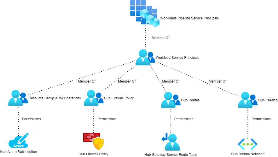
The service principals for all workloads will be added to an Azure AD group (Workloads Pipeline Service Principals in the above diagram). That group is nested into 4 other AAD security groups:
Resource Group ARM Operations: This is granted the CUSTOM – ARM Deployment Operator role on the hub resource group.
Hub Firewall Policy: This is granted the CUSTOM – Azure Firewall Policy Rule Collection Group Administrator role on the Azure Firewalll Policy that is associated with the hub Azure Firewall.
Hub Routes: This is granted the CUSTOM – Azure Route Table Routes Administrator role on the GattewaySubnet route table.
Hub Peering: This is granted the CUSTOM – Virtual Network Peering Administrator role on the hub virtual network.
Deploy The Workload
The workload now has the required permissions to deploy the workload and make modifications in the hub to connect the hub to the outside world.
In this post, I will quickly introduce you to a new kind of Route Table in Microsoft Azure that has been recently introduced by Azure Virtual WAN – and hence is included in the newly generally available Secured Virtual Hub.
The Old “Subnet” Route Table
This Route Table, which I will call “Subnet Route Table” (derived from the ARM name) is a simple resource that we associate with a subnet. It contains User-Defined Routes that force traffic to flow in desirable directions, typically when we use some kind of firewall appliance (Azure Firewall or third-party) or a third-party routing appliance. route The design is simple enough:
Name: A user-friendly name
Prefix: The CIDR you want to get to
Next Hop Type: What kind of “router” is the next hop, e.g. Virtual Network, Internet, or Virtual Appliance
Next Hop IP Address: Used when Next Hop Type is Virtual Appliance (any firewall or third-party router)
Azure Virtual WAN Hub
Microsoft introduced Azure Virtual WAN quite a while ago (by Cloud standards), but few still have heard of it, possibly because of how it was originally marketed as an SD-WAN solution compatible originally with just a few on-prem SD-WAN vendors (now a much bigger list). Today it supports IKEv1 and IKEv2 site-to-site VPN, point-to-site VPN, and ExpressRoute Standard (and higher). You might already be familiar with setting up a hub in a hub-and-spoke: you have to create the virtual network, the Route Table for inbound traffic, the firewall, etc. Azure Virtual WAN converts the hub into an appliance-like experience surfacing just two resources: the Virtual WAN (typically 1 global resource per organisation) and the hub (one per Azure region). Peering, routing, connectivity are all simplified.
A more recent change has been the Secured Virtual Hub, where Azure Firewall is a part of the Virtual WAN Hub; this was announced at Ignite and has just gone GA. Choosing the Secured Virtual Hub option adds security to the Virtual WAN Hub. Don’t worry, though, if you prefer a third-party firewall; the new routing model in Azure Virtual WAN Hub allows you to deploy your firewall into a dedicated spoke virtual network and route your isolated traffic through there.
The New Route Tables
There are two new kinds of route table added by the Virtual WAN Hub, or Virtual Hub, both of which are created in the Virtual Hub as sub-resources.
The routing rule setup here is similar to the Subnet Route Table, specifying where you want to get to (CIDR, resource ID, or service), the next hop, and a next hop IP address.
Virtual WAN Route Table
The Virtual WAN Route Table is created as a sub resource of the Virtual Hub but it has a different purpose. The Virtual Hub is assigned to connections and affects routing from the associated branch offices or virtual networks. Whoa, Finn! There is a lot of terminology in that sentence!
A connection is just that; it is a connection between the hub and another network. Each spoke connected directly to the hub has a connection to the hub – a Virtual WAN Route Table can be associated with each connection. A Virtual WAN Route Table can be associated with 1 virtual network connection, a subset of them, or all of them.
The term “branch offices” refers to sites connected by ExpressRoute, site-to-site VPN, or point-to-site VPN. Those sites also have connections that a Virtual WAN Route Table can be associated with.
This is a much more interesting form of route table. I haven’t had time to fully get under the covers here, but comparing ARM to the UI reveals two methodologies. The Azure Portal reveals one way of visualising routing that I must admit that I find difficult to scale in my mind. The ARM resource looks much more familiar to me, but until I get into a lab and fully test (which I hope I will find some hours to do soon), I cannot completely document.
Here are the basics of what I have gleaned from the documentation, which covers the Azure Portal method:
A Virtual WAN Route Table is associated with a connection. The routes added to this route table will affect the virtual network or branch offices at the far end of the connection from the hub. Propagation is configured in the table, telling the Virtual Hub Route Table where to get routes from, kind of like BGP.
By default, a Virtual WAN Route Table will propagate routes from the default routes in the Virtual Hub. You can add to this and remove from this.
The linked documentation is heavy reading. I’m one of those people that needs to play with this stuff before writing too much in detail – I never trust the docs and, to be honest, this content is complicated, as you can see above.
In this post, I will explain how you can connect multiple Azure hub-and-spoke (virtual data centre) deployments together using Azure networking, even across different Azure regions.
There is a lot to know here so here is some recommended reading that I previously published:
If you are using Azure Virtual WAN Hub then some stuff will be different and that scenario is not covered fully here – Azure Virtual WAN Hub has a preview (today) feature for Any-to-Any routing.
The Scenario
In this case, there are two hub-and-spoke deployments:
Blue: Multiple virtual networks covered by the CIDR of 10.1.0.0/16
Green: Another set of multiple virtual networks covered by the CIDR of 10.2.0.0/16
I’m being strategic with the addressing of each hub-and-spoke deployment, ensuring that a single CIDR will include the hub and all spokes of a single deployment – this will come in handy when we look at User-Defined Routes.
Either of these hub-and-spoke deployments could be in the same region or even in different Azure regions. It is desired that if:
Any spoke wishes to talk to another spoke it will route through the local firewall in the local hub.
All traffic coming into a spoke from an outside source, such as the other hub-and-spoke, must route through the local firewall in the local hub.
That would mean that Spoke 1 must route through Hub 1 and then Hub 2 to talk to Spoke 4. The firewall can be a third-party appliance or the Azure Firewall.
Core Routing
Each subnet in each spoke needs a route to the outside world (0.0.0.0/0) via the local firewall. For example:
The Blue firewall backend/private IP address is 10.1.0.132
A Route Table for each subnet is created in the Blue deployment and has a route to 0.0.0.0/0 via a virtual appliance with an IP address of 10.1.0.132
The Greenfirewall backend/private IP address is 10.2.0.132
A Route Table for each subnet is created in the Green deployment and has a route to 0.0.0.0/0 via a virtual appliance with an IP address of 10.2.0.132
Note: Some network-connected PaaS services, e.g. API Management or SQL Managed Instance, require additional routes to the “control plane” that will bypass the local firewall.
Site-to-Site VPN
In this scenario, the organisation is connecting on-premises networks to 1 or more of the hub-and-spoke deployments with a site-to-site VPN connection. That connection goes to the hub of Blue and to Green hubs.
To connect Blue and Green you will need to configure VNet Peering, which can work inside a region or across regions (using Microsoft’s low latency WAN, the second-largest private WAN on the planet). Each end of peering needs the following settings (the names of the settings change so I’m not checking their exact naming):
Enabled: Yes
Allow Transit: Yes
Use Remote Gateway: No
Allow Gateway Sharing: No
Let’s go back and do some routing theory!
That peering connection will add a hidden Default (“system”) route to each subnet in the hub subnets:
Blue hub subnets: A route to 10.2.0.0/24
Green hub subnets: A route to 10.1.0.0/24
Now imagine you are a packet in Spoke 1 trying to get to Spoke 4. You’re sent to the firewall in Blue Hub 1. The firewall lets the traffic out (if a rule allows it) and now the packet sits in the egress/frontend/firewall subnet and is trying to find a route to 10.2.2.0/24. The peering-created Default route covers 10.2.0.0/24 but not the subnet for Spoke 4. So that means the default route to 0.0.0.0/0 (Internet) will be used and the packet is lost.
To fix this you will need to add a Route Table to the egress/frontend/firewall subnet in each hub:
Blue firewall subnet Route Table: 10.2.0.0/16 via virtual appliance 10.2.0.132
Red firewall subnet Route Table: 10.1.0.0/16 via virtual appliance 10.1.0.132
Thanks to my clever addressing of each hub-and-spoke, a single route will cover all packets leaving Blue and trying to get to any spoke in Red and vice-versa.
ExpressRoute
Now the customer has decided to use ExpressRoute to connect to Azure – Sweet! But guess what – you don’t need 1 expensive circuit to each hub-and-spoke.
You can share a single circuit across multiple ExpressRoute gateways:
ExpressRoute Standard: Up to 10 simultaneous connections to Virtual Network Gateways in 1+ regions in the same geopolitical region.
ExpressRoute Premium: Up to 100 simultaneous connections to Virtual Network Gateways in 1+ regions in any geopolitical region.
FYI, ExpressRoute connections to the Azure Virtual WAN Hub must be of the Premium SKU.
ExpressRoute is powered by BGP. All the on-premises routes that are advertised propagate through the ISP to the Microsoft edge router (“meet-me”) in the edge data centre. For example, if I want an ExpressRoute circuit to Azure West Europe (Middenmeer, Netherlands – not Amsterdam) I will probably (not always) get a circuit to the POP or edge data centre in Amsterdam. That gets me a physical low-latency connection onto the Microsoft WAN – and my BGP routes get to the meet-me router in Amsterdam. Now I can route to locations on that WAN. If I connect a VNet Gateway to that circuit to Blue in Azure West Europe, then my BGP routes will propagate from the meet-me router to the GatewaySubnet in the Blue hub, and then on to my firewall subnet.
BGP propagation is disabled in the spoke Route Tables to ensure all outbound flows go through the local firewall.
But that is not the extent of things! The hub-and-spoke peering connections allow Gateway Sharing from the hub and Use Remote Gateway from the spoke. With that configuration, BGP routes to the spoke get propagated to the GatewaySubnet in the hub, then to the meet-me router, through the ISP and then to the on-premises network. This is what our solution is based on.
Let’s imagine that the Green deployment is in North Europe (Dublin, Ireland). I could get a second ExpressRoute connection but:
That will add cost
Not give me the clever solution that I want – but I could work around that with ExpressRoute Global Reach
I’m going to keep this simple – by the way, if I wanted Green to be in a different geopolitical region such as East US 2 then I could use ExpressRoute Premium to make this work.
In the Green hub, the Virtual Network Gateway will connect to the existing ExpressRoute circuit – no more money to the ISP! That means Green will connect to the same meet-me router as Blue. The on-premises routes will get into Green the exact same way as with Blue. And the routes to the Green spokes will also propagate down to on-premises via the meet-me router. That meet-me router knows all about the subnets in Blue and Green. And guess what BGP routers do? They propagate – so, the routes to all of the Blue subnets propagate to Green and vice-versa with the next hop (after the Virtual Network Gateway) being the meet-me router. There are no Route Tables or peering required in the hubs – it just works!
Now the path from Blue Spoke 1 to Green Spoke 4 is Blue Hub Firewall, Blue Virtual Network Gateway, <the Microsoft WAN>, Microsoft (meet-me) Router, <the Microsoft WAN>, Green Virtual Network Gateway, Green Hub Firewall, Green Spoke 4.
There are ways to make this scenario more interesting. Let’s say I have an office in London and I want to use Microsoft Azure. Some stuff will reside in UK South for compliance or performance reasons. But UK South is not a “hero region” as Microsoft calls them. There might be more advanced features that I want to use that are only in West Europe. I could use two ExpressRoute circuits, one to UK South and one to West Europe. Or I could set up a single circuit to London to get me onto the Microsoft WAN and connected this circuit to both of my deployments in UK South and West Europe. I have a quicker route going Office > ISP > London edge data center > Azure West Europe than from Office > ISP > Amsterdam edge data center > Azure West Europe because I have reduced the latency between me and West Europe by reducing the length of the ISP circuit and using the more-direct Microsoft WAN. Just like with Azure Front Door, you want to get onto the Microsoft WAN as quickly as possible and let it get you to your destination as quickly as possible.