In this post, I am going to share a process for designing a hub virtual network for a hub & spoke secured virtual network deployment in Microsoft Azure.
The process I lay out in this document will not work for everyone.I think, based experience, that very few organisations will find exceptions to this process.
What Is And Is Not In This Post
This post is going to focus on the process of designing a hub virtual network. You will not find a design here … that will come in a later post.
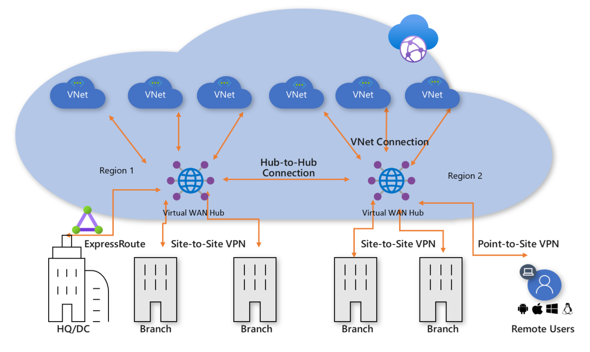
You will also not find any mention of Azure Virtual WAN. You DO NOT need to use Azure Virtual WAN to do SD-WAN, despite the claptrap on Microsoft documentation on this topic. Virtual WAN also:
- Restricts your options on architecture, features, and network design.
- Is a nightmare to troubleshoot because the underlying virtual network is hidden in a Microsoft tenant.
Rules Of Engagement
The hub will be your network core in a network stamp: a hub & spoke. The hub & spoke will contain networks in a single region, following concepts:
- Resilience & independence: Workloads in a spoke in North Europe should not depend on a hub in West Europe.
- Micro-segmentation: Workloads in North Europe trying to access workloads in West Europe should go through a secure route via hubs in each region.
- Performance: Workload A in North Europe should not go through a hub in West Europe to reach Workload B in North Europe.
- Cost Management: Minimise global VNet peering to just what is necessary. Enable costs of hubs to be split into different parts of the organisation.
- Delegation of Duty: If there are different network teams, enable each team to manage their hubs.
- Minimised Resources: The hub has roles only of transit, connectivity, and security. Do not place compute or other resources into the hub; this is to minimise security/networking complexity and increase predictability.
A Hub Design Process
The core of our Azure network will have very little in the way of resources. What can be (not “must be”)included in that hub can be thought of as functions:
- Site-to-site networking: VPN, ExpressRoute, and SD-WAN.
- Point-to-site VPN: Enabling individuals to connect to the Azure networks using a VPN client on their device.
- Firewall: Providing security for ingress, egress, and inter-workload communications.
- Virtual Machines: Reduce costs of secured RDP/SSH by deploying Azure Bastion in the hub.
If we are doing a high-level design, we have a two questions that we will ask about each of thse functions:
- Is the function required?
- What technology will be used?
We won’t get into tiers/SKUs, features, or configurations just yet; that’s when we get into low-level or detailed design.
One can use the following flow chart to figure out what to use – it’s a bit of an eye test so you might need to open the image in another tab:

Site-to-Site (S2S) Networking
While it is very commonly used, not every organisation requires site-to-site connectivity to Azure.
For example, I had a migration customer that was (correctly) modernising to the “top tier” of cloud computing by migrating from legacy apps to SaaS. They wanted to re-implement an SD-WAN for over 100 offices to connect their new and small Azure footprint. I was the lead designer so I knew their connectivity requirements – they were going to use Azure Virtual Desktop (AVD) only to connect to their remaining legacy apps. AVD doesn’t need a site-to-site connection. I was able to save that organisation from entering into a costly managed SD-WAN services contract and instead focus on Internet connectivity – not long later they shutdown their Azure footprint when SaaS aleternatives were found for the the last legacy applications.
If we establish that site-to-site connectivity is required then we must ask the first question:
Are latency and SLA important?
If the answer to either of these items is “yes” then there is no choice: An ExpressRoute Virtual Network Gateway is required.
If the answer is no, then we are looking at some kind of VPN connectivity. We can ask another question to determine the type of solution:
Will there be a small number of VPN connections?
If a small number of VPN connections is required, the Azure VPN Virtual Network Gateway is suitable – consider the SKUs/sizes and complexities of management to determine what “a small number” is.
If you determine that the VPN Virtual Network Gateway is unsuitable then an SD-WAN network virtual appliance (NVA) should be used. Note that it would be recommended to deploy Azure Route Server with a third-party VPN/SD-WAN appliance to enable propagation network prefixes:
- Azure > SD-WAN
- SD-WAN > Azure
You may find that you need one or more of the above solutions! For example:
- Some ExpressRoute customers may opt to deploy a parallel VPN tunnel with an identical routing configuration over a completely different ISP. This enables automatic failover from ExpressRoute to VPN in the event of a circuit failure.
- An SD-WAN customer may also have ExpressRoute for some offices/workloads where SLA or latency are important. Another consideration may be that one workload has other technical requirements that only ExpressRoute (Direct) can service such as very high throughput.
You have one more question to ask after you have picked the site-to-site component(s):
Will you require site-to-site transit through Azure via the site-to-site network connections?
In other words, should Remote Site A be able to route to Remote Site B using your Azure site-to-site connections? If the answer is yes then you must deploy Azure Route Server to enable that routing.
Point-To-Site (P2S) VPN
I personally have not deployed very much of this solution but I do hear it being discussed quite a bit. Some organisations must enable users (or external suppliers) to create a VPN connection from their individual devices to Azure. If this is required then you must ask:
Is the scenario(s) simple?
I’ve kept that vague because the problem is vague. There are two solutions with one being overly-simplistic in capabilities and the other being more fully-featured.
The Azure VPN Gateway (also used for site-to-site VPN) offers a very available (Azure resource) solution for P2S VPN. It offers different configuration for authentication and device support. But it is very limited. For example, it has no routing rules to restrict which users get access to which networks. This means that if you grant network (firewall/NSG) access to one user via the VPN address pool, you must grant the same access to all users, which is clearly pretty poor if you have many types/roles of remote VPN clients (IT, developer of workload X, developer of workload Y, Vendor A, Vendor B, etc).
In such scenarios, one should consider a third-party NVA for point-to-site networking. Third-party NVAs may offer more features for P2S VPN than the VPN Virtual Network Gateway.
A P2S NVA may reside in the same hub as a VPN Virtual Network Gateway (and other S2S solutions).
It’s not in the diagram but you should also consider Entra Global Secure Access as an alternative to P2S VPN. The Private Network Connector would be deployed in a spoke(s), not the hub.
Firewall
Is a firewall required? The correct answer for anyone considering a hub & spoke architecutre should be “of course it is”. But you might not like security, so we’ll ask that question anyway.
Once you determine that security is important to your employer, you must ask yourself:
Shall I use a native PaaS firewall?
The native PaaS solution in Azure is Azure Firewall. I have many technical reasons to prefer Azure Firewall over third-party alternatives. For consultants, a useful attribute of Azure Firewall is that you can skill up on one solution that you can implement/use/manage for many customers and projects (migrations) won’t face repeated delays as you wait on others to implement rules in third-party firewalls.
If you want to use a different firewall then you are free to do so.
If you are using Azure Firewall then there is a follow-up question if there will be S2S network connections:
Are the remote networks using non-RFC1918 address prefixes?
In other words, do the remote networks use address prefixes outside of:
- 192.168.0.0/16
- 172.16.0.0/12
- 10.0.0.0/8
If they do then Azure Firewal requires some configuration because traffic to non-RFC1918 prefixes is forced to the Internet by default – they are Internet addresses after all! You can statically configure the prefixes if they do not change. Or …
- If you are using Azure Route Server
- The prefixes can change a lot thanks to scenarios such as acquisition or rapid growth
… you can (in preview today) configure integration between Azure Firewall and Azure Route Server so the firewall dynamically learns the address prefixes from the remote networks.
Virtual Machines
Do not put compute in the hub!
This scenario asks:
Will any of the workloads in your spoke virtual networks have virtual machines?
You will have virtual machines even if you “ban” virtual machines – I guarantee that they will eventually appear for things like security solutions, self-hosted agents, Azure Virtual Desktop, AKS, and so on.
Unfortunately, many consider secure remote access (SSH/RDP) to be opening a port in the firewall for TCP 22/3389. That is not considered secure because those protocols can be and have been attacked. In the past, those who took security seriously used a dedicated “jump box” or “bastion host” to isolate vulnerable on-premises machines from assets in the data centre. We can use the same process with Azure Bastion where there is no IaaS requirement – we leverage Entra security features to authenticate the connection request and the guest OS credentials to verify VM access.
One can deploy Bastion in a spoke – that is perfectly valid for some scenarios. However, many important features are only in the paid-for SKUs so you might wish to deploy a shared Azure Bastion. Unfortunately, routing restrictions by Bastion prevent deploying a shared Bastion in a spoke, so we have no choice but to deploy a shared Azure Bastion in a hub. If you wish to have a share an Azure Bastion across workloads then it will be the final component in the hub.
If/when Azure Bastion supports route tables in the AzureBastionSubnet I will recommend moving shared Bastion deployments to a spoke – yes, I know that we can do that with Azure Virtual WAN but there are many things that we cannot do with Azure Virtual WAN.
You could consider a third-party alterantive or a DIY bastion solution. If so, place that into a spoke because it will be compute-based.
Wrapping Up
As you can see, the high-level design of the hub is very simple.

There are few functions in it because when you understand Azure virtual networks, routing, and NSGs, then you understand that designing a secure network should not be complex. Complexity is the natural predator of manageability and dependable security. There is a little more detail when we get into a low-level or detailed design, but that’s a topic for another day.