This post will explain how a well-designed, secured, governed and managed network design plays a foundational role in digital transformation and cloud enablement.
Cloud Adoption Versus Cloud Migration
What? Aidan – I thought this was a post about Azure networking!
Yes, it is … but you’ll have to join me on this journey. Lately, I’ve been using the “we need to step back and think about why we’re doing any of this” line quite a bit. The context of that line changes, but the message remains consistent.
Why did we go to The Cloud (Azure in our case)? For many, the reason is something like “I was told to”, “we were leaving our old hosting company”, or “our hardware support ended”. Those reasons triggered what I call a cloud migration project. I’ve done a LOT of those projects – thanks to scope limitations in the engagement, forced either by poorly advised customers (that lead to restricted tenders) or salespeople who refused to have a larger conversation.
Many organisations with internal developers that do a cloud migration end up in a situation 18-24 months later. Developers refuse to deploy into “IT’s cloud”. This is because IT has recreated its old data centre in Azure, along with the restrictions, controls, and lack of trust. We were told “cloud is how you work, not where you work”, but not many people heard that message. We end up with situations where businesses have paid for Azure, but developers don’t get the Cloud; they get IT-driven and IT-restricted virtualisation in Azure.
Cloud Adoption is a change journey, as documented by the Cloud Adoption Framework. We are supposed to:
- Understand why the business (not IT) wants to use the Cloud
- Create a cloud strategy for the organisation
- Define and enable a new way of delivering cross-functional digital services.
- Do all the other technical stuff that we focus on, with the architecture based on the above.
Steps 1 and 2 (CAF Strategy and Phase) are the keys to cloud adoption success. In theory, if we do everything correctly:
- The developers want to adopt the new cloud environment because it enables their mission.
- The business sees a return on the investment with faster innovation of digital services.
Where Does Networking Come Into This?
Pretty much every customer I’ve dealt with wants to improve their security for business protection or to meet compliance requirements. That typically results in larger usage of Virtual Networks. Many customers end up recreating their data centre networks in Azure; they create 1 Virtual Network (spoke) for each VLAN:
- DMZ
- Regular zone
- Secure Zone
Or maybe they have:
- Dev
- Test
- Production
Each of these networks shares various traits:
- A big virtual network with many subnets
- Managed by the central IT infrastructure
I can go into all the security and complexity flaws that result from this too-common design pattern. But my focus is on cloud adoption in this post:
- Developers are actively prevented from having network access/control. They rely on helpdesk tickets to get anything done – what happened to the essential cloud trait of “on-demand self-service”?
- Subscriptions are filled with dozens of resource groups. Access is granted on a per-resource group granularity, which complicates and slows things down.
- The desire for more security is gradually eroded due to operational complexity and constant delegation of rights with complicated granularity.
So, believe it or not, Azure networking is our canary in the mine. I have used, and I continue to use this reliable little bird to smell out operational/security failures in customers’ Azure environments.
Now, you know how I can detect adoption problems from the floor up. Next I want to explain how I can architect the Azure network to solve these issues.
Landing Zones
Let’s bend some minds. 8-ish years ago, I started working on a new “standard design” for my employer (a consulting company) with a fellow principal consultant. We mutually came to the table with an alternative subscription strategy than usual. The norm was that each of the above traditional spoke VNets would be aligned with a subscription each. That results in very few subscriptions, with demands for complicated role delegations, tagging, cost management, and so on. We switched to a 1 subscription/workload (application/service) approach; this new level of granularity:
- Required 1 small Virtual Network where networking is required
- Developer/operator role delegations are done once per subscription
- Cost management is done per subscription (Budgets) with much less tagging for metadata
- Easier operations with fewer mistakes through subscription selection in Azure Portal/PowerShell/CLI/etc. The resource groups in the subscription are related to only that workload.
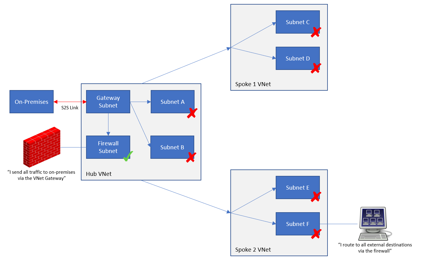
- The security boundary is much smaller. The access boundary is the single workload. Any VNet-based workloads must route via the hub firewall to reach any other workload, subject to rules and IDPS inspection.
Microsoft introduced the concept of landing zones a few years ago, which uses the same subscription/workload approach:
- Platform landing zone: A subscription that offers shared infrastructure, such as a hub, a shared Application Gateway/WAF, Active Directory Domain Controllers, DNS, etc.
- Application landing zone: A subscription that hosts a single application/service/workload.
Like with my approach, each landing zone has a Virtual Network (if required) that is:
- Sized according to the workload architecture with some spare capacity.
- Peered with the hub, with the egress path from the workload being via the hub firewall.
Security & Governance
Let’s consider some things:
- The business requires governance to manage IT and to ensure regulatory compliance.
- IT security must protect the business, customers, vendors, etc.
- We have many workloads/subscriptions.
We cannot have 1 policy for everything – sometimes we have business/operational reasons to have more-strict policies or less-strict policies. For example, we might require more Defender for Cloud features in some workloads or allow PaaS public endpoints in others.
Microsoft gave us Enterprise Scale around 5 years ago. This reference architecture (with supplied templated deployments) offers a subscription categorisation approach using Management Groups:
- Corporate: Workloads that can connect to other networks.
- Online: Workloads that have an online presence and should not connect to other workloads.
Azure Policy is used to enforce the standards for each Management Group.
I don’t know about you, but I have never seen such a binary requirement in the real world. I’ve seen many people discuss/use a third Management Group called Hybrid; they wonder how to build the policies to enforce the requirements.
In the real world, just about everything is shades of grey when it comes to connectivity. I’ve had ultra-secure workloads with web interfaces. I’ve had low-end workloads with high security. And I can guarantee you that sensitive workloads have compelling business reasons to be both online and integrated with traditional private-protocol connectivity.
I thought about this last year and came up with a different approach. We can use CAF’s operational methodologies to develop a tiered, documented, and implemented policy that aligns with the organisation’s governance, security, and management requirements. I suggested that we would have three tiers (names are irrelevant):
- Gold: The strictest policies
- Silver: Medium-level policies, containing the most workloads
- Bronze: The most relaxed policies
The result is 3 Management Groups (above), each with Azure Policy automatically auditing/enforcing the designed and continuously improved requirements.
The new (CAF Plan) operational model would introduce a step to categorise the workload based on security risks, governance requirements, and management needs. Each workload would be placed in the correct Management Group with policies.
The policies give us automation and guardrails. For example, where appropriate, we can:
- Restrict regions.
- Ban public IP association with NICs
- Disable public endpoints
- Enable Defender for Cloud plans
- Force VNet Flow Logging
- Configure diagnostics settings
- Enable VNet Flow Logs
- And much more
The key to this is momentum. My approach is “minimum viable product” (MVP). For example, I had a 30-minute call with a customer last year and designed their starter policies. Now they (should) run regular reviews to assess the policies/risks/requirements and expand the policies/implementations. We didn’t freeze for 2 years to build a policy. We got some essentials in place and we carried on with getting results for the business.
Now, let’s get back to networking!
At-Scale Network Configuration And Enforcement
Developers, operators, and (rival) service providers are empowered to build in the Azure environment with a new guardrail-protected landing zone approach. How do we ensure that their Virtual Networks are built correctly?
We can use Azure Virtual Network Manager (AVNM).
Note that the horrid per-subscription pricing for AVNM was replaced a long time ago. Please go back and reassess the pricing before you run away.
AVNM gives us policy-driven:
- Discovery and grouping of Virtual Networks for granular policy assignments
- Peering with a hub and mesh capabilities
- Route Table deployment/association with User-Defined Routes (UDRs)
- Security Admin Rules that are processed before NSG rules with override capabilities
- IP Address Management (IPAM) to provide approved, non-repeating IP prefixes for new networks and to manage their lifecycle
In short, if you deploy a VNet, I can:
- Get an approved IP prefix for the Virtual Network
- Use Azure Policy to automatically configure/enforce things like VNet Flow Logs and DNS settings
- Use AVNM to correctly connect, route, and secure your VNet
To quote Van Halen: “they got you coming in, and they got you going out”. I always did prefer “Van Hagar” 🙂
Summary
A legacy, cable-oriented, on-prem network in Azure indicates that the organisation has not modernised how digital services are created, operated, and delivered to the business. In short, the business is paying for the cloud but is getting remotely hosted Hyper-V.
We can enable modern collaborative working processes by modernising our designs. Using application landing zones will create a new form of granularity for all aspects of infrastructure, security, governance, and management. We can use the governance features to create the guardrails and some of the autmations. We can use Azure Virtual Network Manager (AVNM) to ensure a good Virtual Network deployment.
If You Want To Learn More
Contact me via my consulting company, Cloud Mechanix, if you would like to learn how I can help you with this design pattern.