Enabling DevSecOps with Azure Firewall

In this post, I will share how you can implement DevSecOps with Azure Firewall, with links to a bunch of working Bicep files to deploy the infrastructure-as-code (IaC) templates.

This example uses a “legacy” hub and spoke – one where the hub is VNet-based and not based on Azure Virtual WAN Hub. I’ll try to find some time to work on the code for that one.

The Concept

Hold on, because there’s a bunch of things to understand!

DevSecOps

The DevSecOps methodology is more than just IaC. It’s a combination of people, processes, and technology to enable a fail-fast agile delivery of workloads/applications to the business. I discussed here how DevSecOps can be used to remove the friction of IT to deliver on the promises of the Cloud.

The Azure features that this design is based on are discussed in concept here. The idea is that we want to enable Devs/Ops/Security to manage firewall rules in the workload’s Git repository (repo). This breaks the traditional model where the rules are located in a central location. The important thing is not the location of the rules, but the processes that manage the rules (change control through Git repo pull request reviews) and who (the reviewers, including the architects, firewall admins, security admins, etc).

So what we are doing is taking the firewall rules for the workload and placing them in with the workload’s code. NSG rules are probably already there. Now, we’re putting the Azure Firewall rules for the workload in the workload repo too. This is all made possible thanks to changes that were made to Azure Firewall Policy (Azure Firewall Manager) Rules Collection Groups – I use one Rules Collection Group for each workload and all the rules that enable that workload are placed in that Rules Collection Group. No changes will make it to the trunk branch (deployment action/pipelines look for changes here to trigger a deployment) without approval by all the necessary parties – this means that the firewall admins are still in control, but they don’t necessarily need to write the rules themselves … and the devs/operators might even write the rules, subject to review!

This is the killer reason to choose Azure Firewall over NVAs – the ability to not only deploy the firewall resource, but to manage the entire configuration and rule sets as code, and to break that all out in a controlled way to make the enterprise more agile.

Other Bits

If you’ve read my posts on Azure routing (How to Troubleshoot Azure Routing? and BGP with Microsoft Azure Virtual Networks & Firewalls) then you’ll understand that there’s more going on than just firewall rules. Packets won’t magically flow through your firewall just because it’s in the middle of your diagram!

The spoke or workload will also need to deploy:

  • A peering connection to the hub, enabling connectivity with the hub and the firewall. All traffic leaving the spoke will route through the firewall thanks to a user-defined route in the spoke subnet route table. Peering is a two-way connection. The workload will include some bicep to deploy the spoke-hub and the hub-spoke connections.
  • A route for the GatewaySubnet route table in the hub. This is required to route traffic to the spoke address prefix(es) through the Azure Firewall so on-premises>spoke traffic is correctly inspected and filtered by the firewall.

The IaC

In this section, I’ll explain the code layout and placement.

My Code

You can find my public repo, containing all the Bicep code here. Please feel free to download and use.

The Git Repo Design

You will have two Git repos:

  1. The first repo is for the hub. This repo will contain the code for the hub, including:
    • The hub VNet.
    • The Hub VNet Gateway.
    • The GatewaySubnet Route Table.
    • The Azure Firewall.
    • The Azure Firewall Policy that manages the Azure Firewall.
  2. The second repo is for the spoke. This skeleton example workload contains:

Action/Pipeline Permissions

I have written a more detailed update on this section, which can be found here

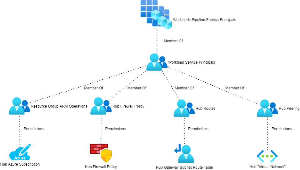
Each Git repo needs to authenticate with Azure to deploy/modify resources. Each repo should have a service principal in Azure AD. That service principal will be used to authenticate the deployment, executed by a GitHub action or a DevOps pipeline. You should restrict what rights the service principal will require. I haven’t worked out the exact minimum permissions, but the high-level requirements are documented below:


Trunk Branch Protection &  Pull Request

Some of you might be worried now – what’s to stop a developer/operator working on Workload A from accidentally creating rules that affect Workload X?

This is exactly why you implement standard practices on the Git repos:

  • Protect the Trunk branch: This means that no one can just update the version of the code that is deployed to your firewall or hub. If you want to create an updated, you have to create a branch of the trunk, make your edits in that trunk, and submit the changes to be merged into trunk as a pull request.
  • Enable pull request reviews: Select a panel of people that will review changes that are submitted as pull requests to the trunk. In our scenario, this should include the firewall admin(s), security admin(s), network admin(s), and maybe the platform & workload architects.

Now, I can only submit a suggested set of rules (and route/peering) changes that must be approved by the necessary people. I can still create my code without delay, but a change control and rollback process has taken control. Obviously, this means that there should be SLAs on the review/approval process and guidance on pull request, approval, and rejection actions.

And There You Have It

Now you have the design and the Bicep code to enable DevSecOps with Azure Firewall.

Connecting Azure Hub-And-Spoke Architectures Together

In this post, I will explain how you can connect multiple Azure hub-and-spoke (virtual data centre) deployments together using Azure networking, even across different Azure regions.

There is a lot to know here so here is some recommended reading that I previously published:

If you are using Azure Virtual WAN Hub then some stuff will be different and that scenario is not covered fully here – Azure Virtual WAN Hub has a preview (today) feature for Any-to-Any routing.

The Scenario

In this case, there are two hub-and-spoke deployments:

  • Blue: Multiple virtual networks covered by the CIDR of 10.1.0.0/16
  • Green: Another set of multiple virtual networks covered by the CIDR of 10.2.0.0/16

I’m being strategic with the addressing of each hub-and-spoke deployment, ensuring that a single CIDR will include the hub and all spokes of a single deployment – this will come in handy when we look at User-Defined Routes.

Either of these hub-and-spoke deployments could be in the same region or even in different Azure regions. It is desired that if:

  • Any spoke wishes to talk to another spoke it will route through the local firewall in the local hub.
  • All traffic coming into a spoke from an outside source, such as the other hub-and-spoke, must route through the local firewall in the local hub.

That would mean that Spoke 1 must route through Hub 1 and then Hub 2 to talk to Spoke 4. The firewall can be a third-party appliance or the Azure Firewall.

Core Routing

Each subnet in each spoke needs a route to the outside world (0.0.0.0/0) via the local firewall. For example:

  • The Blue firewall backend/private IP address is 10.1.0.132
  • A Route Table for each subnet is created in the Blue deployment and has a route to 0.0.0.0/0 via a virtual appliance with an IP address of 10.1.0.132
  • The Greenfirewall backend/private IP address is 10.2.0.132
  • A Route Table for each subnet is created in the Green deployment and has a route to 0.0.0.0/0 via a virtual appliance with an IP address of 10.2.0.132

Note: Some network-connected PaaS services, e.g. API Management or SQL Managed Instance, require additional routes to the “control plane” that will bypass the local firewall.

Site-to-Site VPN

In this scenario, the organisation is connecting on-premises networks to 1 or more of the hub-and-spoke deployments with a site-to-site VPN connection. That connection goes to the hub of Blue and to Green hubs.

To connect Blue and Green you will need to configure VNet Peering, which can work inside a region or across regions (using Microsoft’s low latency WAN, the second-largest private WAN on the planet). Each end of peering needs the following settings (the names of the settings change so I’m not checking their exact naming):

  • Enabled: Yes
  • Allow Transit: Yes
  • Use Remote Gateway: No
  • Allow Gateway Sharing: No

Let’s go back and do some routing theory!

That peering connection will add a hidden Default (“system”) route to each subnet in the hub subnets:

  • Blue hub subnets: A route to 10.2.0.0/24
  • Green hub subnets: A route to 10.1.0.0/24

Now imagine you are a packet in Spoke 1 trying to get to Spoke 4. You’re sent to the firewall in Blue Hub 1. The firewall lets the traffic out (if a rule allows it) and now the packet sits in the egress/frontend/firewall subnet and is trying to find a route to 10.2.2.0/24. The peering-created Default route covers 10.2.0.0/24 but not the subnet for Spoke 4. So that means the default route to 0.0.0.0/0 (Internet) will be used and the packet is lost.

To fix this you will need to add a Route Table to the egress/frontend/firewall subnet in each hub:

  • Blue firewall subnet Route Table: 10.2.0.0/16 via virtual appliance 10.2.0.132
  • Red firewall subnet Route Table: 10.1.0.0/16 via virtual appliance 10.1.0.132

Thanks to my clever addressing of each hub-and-spoke, a single route will cover all packets leaving Blue and trying to get to any spoke in Red and vice-versa.

ExpressRoute

Now the customer has decided to use ExpressRoute to connect to Azure – Sweet! But guess what – you don’t need 1 expensive circuit to each hub-and-spoke.

You can share a single circuit across multiple ExpressRoute gateways:

  • ExpressRoute Standard: Up to 10 simultaneous connections to Virtual Network Gateways in 1+ regions in the same geopolitical region.
  • ExpressRoute Premium: Up to 100 simultaneous connections to Virtual Network Gateways in 1+ regions in any geopolitical region.

FYI, ExpressRoute connections to the Azure Virtual WAN Hub must be of the Premium SKU.

ExpressRoute is powered by BGP. All the on-premises routes that are advertised propagate through the ISP to the Microsoft edge router (“meet-me”) in the edge data centre. For example, if I want an ExpressRoute circuit to Azure West Europe (Middenmeer, Netherlands – not Amsterdam) I will probably (not always) get a circuit to the POP or edge data centre in Amsterdam. That gets me a physical low-latency connection onto the Microsoft WAN – and my BGP routes get to the meet-me router in Amsterdam. Now I can route to locations on that WAN. If I connect a VNet Gateway to that circuit to Blue in Azure West Europe, then my BGP routes will propagate from the meet-me router to the GatewaySubnet in the Blue hub, and then on to my firewall subnet.

BGP propagation is disabled in the spoke Route Tables to ensure all outbound flows go through the local firewall.

But that is not the extent of things! The hub-and-spoke peering connections allow Gateway Sharing from the hub and Use Remote Gateway from the spoke. With that configuration, BGP routes to the spoke get propagated to the GatewaySubnet in the hub, then to the meet-me router, through the ISP and then to the on-premises network. This is what our solution is based on.

Let’s imagine that the Green deployment is in North Europe (Dublin, Ireland). I could get a second ExpressRoute connection but:

  • That will add cost
  • Not give me the clever solution that I want – but I could work around that with ExpressRoute Global Reach

I’m going to keep this simple – by the way, if I wanted Green to be in a different geopolitical region such as East US 2 then I could use ExpressRoute Premium to make this work.

In the Green hub, the Virtual Network Gateway will connect to the existing ExpressRoute circuit – no more money to the ISP! That means Green will connect to the same meet-me router as Blue. The on-premises routes will get into Green the exact same way as with Blue. And the routes to the Green spokes will also propagate down to on-premises via the meet-me router. That meet-me router knows all about the subnets in Blue and Green. And guess what BGP routers do? They propagate – so, the routes to all of the Blue subnets propagate to Green and vice-versa with the next hop (after the Virtual Network Gateway) being the meet-me router. There are no Route Tables or peering required in the hubs – it just works!

Now the path from Blue Spoke 1 to Green Spoke 4 is Blue Hub Firewall, Blue Virtual Network Gateway, <the Microsoft WAN>, Microsoft (meet-me) Router, <the Microsoft WAN>, Green Virtual Network Gateway, Green Hub Firewall, Green Spoke 4.

There are ways to make this scenario more interesting. Let’s say I have an office in London and I want to use Microsoft Azure. Some stuff will reside in UK South for compliance or performance reasons. But UK South is not a “hero region” as Microsoft calls them. There might be more advanced features that I want to use that are only in West Europe. I could use two ExpressRoute circuits, one to UK South and one to West Europe. Or I could set up a single circuit to London to get me onto the Microsoft WAN and connected this circuit to both of my deployments in UK South and West Europe. I have a quicker route going Office > ISP > London edge data center > Azure West Europe than from Office > ISP > Amsterdam edge data center > Azure West Europe because I have reduced the latency between me and West Europe by reducing the length of the ISP circuit and using the more-direct Microsoft WAN. Just like with Azure Front Door, you want to get onto the Microsoft WAN as quickly as possible and let it get you to your destination as quickly as possible.